Pump Ed 101
Joe Evans, Ph.D
The
members of that family of machines known as "dynamic pumps"
are very different than the cousins that make up the "displacement"
branch of the tree . Unlike the displacement pump, which adds
energy to a fluid only intermittently, dynamic pumps continuously
impart energy into a flowing liquid. One of the primary members
of this family is the centrifugal pump and, although centrifugal force
is actually a farce, this group is still able to meet the
requirements of the definition.
Mechanics is the study of forces and motion. Hydraulics is the branch of mechanics that focuses this study on liquids. And, dynamics is the branch of mechanics and hydraulics that deals with the motion and equilibrium of systems under the action of forces related to motion. Motion and equilibrium are the key words here and they will be our focus. In this short tutorial, we will investigate the "dynamics" that occur within the centrifugal pump from the time a liquid enters the suction until it exits the discharge. I have chosen to present this tutorial in html format so that I can utilize some imbedded animations and also link to several other web sites that offer some additional learning tools that may help clarify certain points. It is also available in pdf format but all of the images will be seen in still life.
Before we enter the world of dynamic pumps lets take a quick look at the displacement pump. The animation to the right is that of a single acting
piston pump and is borrowed from Animated Software
Company. As you can see, one complete operation
(cycle) consists of a suction stroke (piston moves to the left) and a
discharge stroke (piston moves to the right). The suction and
discharge check valves open and close in accordance with the direction
of the piston and liquid movement. This results in the discharge
of a volume of liquid equal to that of the "displacement" of the
cylinder. Although external energy (atmospheric pressure etc.) is
required to bring liquid into the cylinder during the suction stroke, energy is added to the liquid "only"
during the discharge stroke.
single acting
piston pump and is borrowed from Animated Software
Company. As you can see, one complete operation
(cycle) consists of a suction stroke (piston moves to the left) and a
discharge stroke (piston moves to the right). The suction and
discharge check valves open and close in accordance with the direction
of the piston and liquid movement. This results in the discharge
of a volume of liquid equal to that of the "displacement" of the
cylinder. Although external energy (atmospheric pressure etc.) is
required to bring liquid into the cylinder during the suction stroke, energy is added to the liquid "only"
during the discharge stroke.
The flow produced by this simple piston pump is f = d/t where f is flow, d is the volume displaced during the discharge stroke, and t is the unit of time. If d is one gallon and t is one second then flow is equal to 1 gps or 60 gpm. The amount of pressure generated, however, is dictated by the system and it is virtually impossible to calculate the maximum pressure that can be generated. For example, if this pump is filling a tank 231 feet above it, the total system pressure would be 100 psi (elevation) plus the friction generated by the piping. But, suppose that someone closes a valve half way up - - how would the system pressure change? It is totally unpredictable, as it would depend upon the power of the driver and the strength of the materials. In other words, pressure would increase until the driver stalls, the pipe bursts, or some other component fails.
The Role of the Impeller
 The centrifugal pump,
on the other hand, adds energy continuously via its rotating
impeller. The animation to the left, borrowed from Light My Pump, shows a
cross-sectional
view. As the
impeller rotates, water enters the vanes where it is accelerated to its maximum
velocity just as it exits at the periphery of the impeller. The
kinetic energy added by the impeller is then transformed into pressure
energy as water flows through the ever increasing geometry of the
volute. It usually reaches its maximum pressure at the volute
throat where the cutwater directs flow into the discharge.
The centrifugal pump,
on the other hand, adds energy continuously via its rotating
impeller. The animation to the left, borrowed from Light My Pump, shows a
cross-sectional
view. As the
impeller rotates, water enters the vanes where it is accelerated to its maximum
velocity just as it exits at the periphery of the impeller. The
kinetic energy added by the impeller is then transformed into pressure
energy as water flows through the ever increasing geometry of the
volute. It usually reaches its maximum pressure at the volute
throat where the cutwater directs flow into the discharge.
Now, some would lead you to believe that this energy is added via a quantity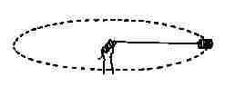 known as centrifugal force.
This force is defined as "center fleeing" and is said to outwardly
accelerate any object that happens to be
traveling in a circle or through an arc. The example to the right
shows
someone swinging a can in a circle. If it is
released, at the exact point shown in the example, centrifugal force
should carry it directly to the right. But in real life, it does
not - - it travels tangent to the circle in which it was swinging.
known as centrifugal force.
This force is defined as "center fleeing" and is said to outwardly
accelerate any object that happens to be
traveling in a circle or through an arc. The example to the right
shows
someone swinging a can in a circle. If it is
released, at the exact point shown in the example, centrifugal force
should carry it directly to the right. But in real life, it does
not - - it travels tangent to the circle in which it was swinging.
 The
animation on the left,
borrowed from Science Joy
Wagon, should
clear this up a bit. It shows two views of a car as it begins to
curve to the left. The bottom view is one from the passenger seat
and the top one is a "bird's eye" view from above. As the car
enters the curve the passenger sees the tape cartridge on the dash
begin to slide to the right and eventually fly out the window.
Upon seeing this the passenger would assume that centrifugal force is
the culprit because he, too would feel some force pulling him to the
right. The bird, however, would notice something quite
different. The bird would see the dash sliding under the tape
as the tape maintained its original direction of travel. Unlike
the car's tires and the road, the light weight tape and the dash
develop very little
friction between them so the tape continues in the same direction it
was traveling before
the car entered the curve. Centrifugal force is one of three
"false" forces found in nature. It's "existence" depends upon
one's point of reference. The force you feel when rounding a
curve is caused by your body trying to act exactly as the tape and the
can did - -
maintain
its original direction of travel.
The
animation on the left,
borrowed from Science Joy
Wagon, should
clear this up a bit. It shows two views of a car as it begins to
curve to the left. The bottom view is one from the passenger seat
and the top one is a "bird's eye" view from above. As the car
enters the curve the passenger sees the tape cartridge on the dash
begin to slide to the right and eventually fly out the window.
Upon seeing this the passenger would assume that centrifugal force is
the culprit because he, too would feel some force pulling him to the
right. The bird, however, would notice something quite
different. The bird would see the dash sliding under the tape
as the tape maintained its original direction of travel. Unlike
the car's tires and the road, the light weight tape and the dash
develop very little
friction between them so the tape continues in the same direction it
was traveling before
the car entered the curve. Centrifugal force is one of three
"false" forces found in nature. It's "existence" depends upon
one's point of reference. The force you feel when rounding a
curve is caused by your body trying to act exactly as the tape and the
can did - -
maintain
its original direction of travel.
Well, if centrifugal force is not responsible for adding kinetic energy - - what is? Just how does that impeller add energy in the form of velocity? We will get to that in a minute but, first, lets outline the steps a liquid encounters as it moves from suction to discharge.
1 Rotation of the impeller and the shape of the vane entrances forces liquid to move from the eye of the impeller into its vanes.
2 During rotation the curved shape of the vanes causes liquid to continue to flow towards the vane exits.
3 This flow causes a partial vacuum at the eye which allows atmospheric or some other, outside pressure to force more liquid into the eye thus regenerating the entire process.
4 As liquid flows through the vanes, it gains velocity and reaches its maximum velocity just as it exits the vanes.
5 Upon exiting the vanes, liquid enters the volute where most of its kinetic energy of motion is transformed into pressure energy.
Now, getting back to our question - - how does the impeller add velocity? Well it is has to do with the ever changing rotational velocity of points along the radius of a spinning disc. Linear velocity is a very straight (pun intended) forward quantity - - when an object moves in a straight line its velocity is simply distance traveled divided by the time it took to get there (v=d/t). Another characteristic is that every part of that object moves at the same velocity. Take an automobile for example - - even though the front bumper will get there first, the back bumper is traveling at the same velocity! This is not the case with rotational motion. When we talk about rotational velocity we usually use the term "rpm" or rotations per minute. That is because every point along the radius of a rotating disc will complete one rotation in the same amount of time. But the distance any point will travel depends upon its location on the radius. The link that you see a couple of lines below will bring up an animation that will put this in perspective. I would like to provide a link to the developer's site but I cannot remember where I found it. I find that, sometimes, my memory is not as good as it used to be. Also, my memory is not as good as it used to be. Anyway, after you click on the link, click on the "line" or "?" button to the left. Then click on the "Play" button. After you have viewed the animation click on your browser's back arrow to return to the tutorial. Click here to see the animation.
What you saw was two lady bugs sitting on a phonograph disc - - one at some distance "R" from the center of the disc and the other at twice that distance. When you hit the play button the disc began to spin and both bugs crossed the "finish" line at the very same time. Their trips, however, were quite different. The circumference of the circle described by the lady bug at point R is equal to 2πR. If we assume that R is one foot then the circumference and the equivalent "straight line" distance traveled is 6.28 feet. At 2R the other lady bug will travel twice that distance or 12.56 feet. Since both complete one rotation in the same amount of time, the bug at point 2R must travel at twice the velocity.
Although simple, rotational motion is more complex that linear motion because the equivalent velocity is always proportional the the radius - - double the radius and the velocity doubles. The same thing happens in a centrifugal pump. As water flows through the vanes of an impeller, it encounters an ever increasing radius that causes velocity to increase proportionally. Its final and also maximum velocity is reached just as it exits the vanes at the periphery or outer most diameter of the impeller. It is in this simple manner that the impeller adds velocity energy to water.
The head produced by a centrifugal pump is proportional to the velocity attained by the water as it exits the vanes at the periphery of the impeller (peripheral velocity). If you double the rotational speed or the diameter of the impeller you double its peripheral velocity. Cut either in half and you reduce the peripheral velocity by one half. The peripheral velocity produced by an impeller is always Cw where C is the circumference and w is the rpm. Since head is based entirely upon velocity, we can easily compute the maximum head that can be produced by an impeller by rearranging the "falling body" equation (v2=2gh). This equation states that the velocity at which an object will strike the ground, near the surface of the earth, is equal to 2gh - - where g is the universal
gravitational constant (32ft/sec/sec) and h is the height of the object
when it was released. This assumes that the object is falling in
a vacuum and encounters no wind resistance.
2gh - - where g is the universal
gravitational constant (32ft/sec/sec) and h is the height of the object
when it was released. This assumes that the object is falling in
a vacuum and encounters no wind resistance.
If we rearrange the equation to solve for height we get h=v2/2g. Lets take a look at a practical example. Suppose we have an impeller that is 9" in diameter and is rotating at 1800 rpm. What is the maximum head it can produce? First we need the circumference of the impeller in feet:
C = πd = 3.14 x 9" = 28.3" = 2.36'
Then we can compute the velocity of the water as it exits the vanes:
v = Cw = 2.36' x 1800 rpm = 4248 ft/min = 70.8 ft/sec
Now we can replace v in our equation with the computed velocity and solve for h:
h= v2/2g = (70.8)2 / (2 x 32) = 5012.64 / 64 = 78.32'
The maximum head that can be produced by a 9" diameter impeller rotating at 1800 rpm is just a tad over 78'. Head varies as the square of a change in rotational speed or impeller diameter (peripheral velocity). Double the speed or diameter and head increases by four. Reduce either by one half and head is reduced to one fourth. One of the interesting things about the equation we just used is that there is no mention of mass or weight. Just as all objects, regardless of their weight, fall at the same rate those same bodies will also reach the same height given the same initial velocity. In the case of the centrifugal pump this means that all liquids, regardless of their weight (specific gravity) will reach the same head in feet even though their pressures in PSI will vary substantially.
The flow produced by an impeller is also proportional to the velocity it attains at the periphery. But, unlike the piston pump there is no simple equation that we can use to calculate it. Flow depends upon the design and dimensions of the vanes. But, once it has been determined by testing, changes will always be directly proportional to a change in rotational speed or impeller diameter (peripheral velocity). Double the rotational speed or diameter and flow doubles - - reduce either by one half and flow is reduced by one half.
The Role of the Volute
The volute houses the impeller and is the "receptacle" for the water exiting the impeller vanes. Its volume is many times that of the
 impeller and its
nearly circular geometry guides the flow from the vane exits to its
discharge. During this trip, the flow encounters an ever
increasing volume and a corresponding reduction in velocity.
impeller and its
nearly circular geometry guides the flow from the vane exits to its
discharge. During this trip, the flow encounters an ever
increasing volume and a corresponding reduction in velocity.
The illustration to the left is a cross section of an end suction pump showing the volute and the impeller. The area just above the discharge, where the volute begins, (about 7 o'clock) is known as the cutwater. Its purpose is to guide water into the discharge and reduce recirculation back into the volute. The colors indicate the velocity of the water at various areas of the volute. Red equates to the highest velocity while blue is the lowest. You will note that the areas of highest velocity occur near the vane exits and the narrow portion of the volute from the cut water to about 10 o'clock. Velocity decreases as the volute volume increases and reaches its lowest level in the area of the discharge. The purpose of the volute is to convert the kinetic energy of velocity to that of pressure. But how does it do this? After all there no moving parts! Well, it has to do with its ever increasing volume and the corresponding decrease in velocity of the water moving through it.
Energy
Water can possess three forms of hydraulic energy - - potential energy due to elevation, kinetic energy due to velocity, and pressure energy due to weight or force. In physics we say that energy can neither be created nor destroyed - - it can only change its state or form. Therefore these three forms of energy must be able to live in harmony and their quantities, at a given point in time, will follow a simple law known as The Conservation of Energy. Now, for our purposes, we can pretty much eliminate potential energy because there is little or no elevation change from a pump's suction to its discharge. But as we saw above, a liquid's velocity undergoes a large change as it moves through the impeller and volute. Since velocity is, in fact, energy it must be replaced by some other form as it decreases. That other form of energy is pressure and it arises of it own accord as the volute volume increases and velocity decreases.
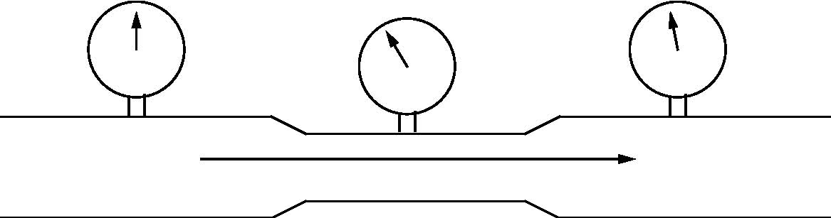 The figure to
the right shows a pipe with water flowing from left ot right at 100
gpm. As water reaches the center of the pipe it encounters a
section that has a reduced diameter but a short distance away the pipe
returns to its original diameter. Notice the three pressure
gauges
- - the one on the left points to 12 o'clock while the one in the
center is at 10 o'clock. The gauge on the right displays just a
little less than the one on the far left. In other words pressure
drops as water enters the constricted area of the pipe but it returns
to nearly its original pressure as it exits the constricted area.
What is happening here?
The figure to
the right shows a pipe with water flowing from left ot right at 100
gpm. As water reaches the center of the pipe it encounters a
section that has a reduced diameter but a short distance away the pipe
returns to its original diameter. Notice the three pressure
gauges
- - the one on the left points to 12 o'clock while the one in the
center is at 10 o'clock. The gauge on the right displays just a
little less than the one on the far left. In other words pressure
drops as water enters the constricted area of the pipe but it returns
to nearly its original pressure as it exits the constricted area.
What is happening here?
Well, if flow is to remain constant (100 gpm) the velocity of the water must increase as it travels through the constricted area of the pipe. We see this in nature when a slow moving river enters and exits a narrow gorge. And, it confirms our statement about energy - - as one form (velocity) increases, another form (pressure) must decrease and vice versa. Bernoulli's theorem states that during steady flow the energy at any point in a conduit is the sum of the velocity energy, pressure energy, and the potential energy due to elevation. It also says the the sum will remain constant if there are no losses.
In our
example above, the small loss in pressure seen in the right hand
portion of the pipe is due to increased friction in the narrow
section. Depending upon the circumstances, pressure loss due to
friction may be a result of the generation and dissipation of heat or
it could be due to a
small increase in velocity due to a change in laminar flow.
As friction increases laminar flow becomes less symmetrical which,
essentially, reduces the diameter of the conduit. Click here
and you will be directed to Mark
Mitchell's web site that illustrates the Bernoulli
Principle. It will allow you to vary pipe
diameters and see the resulting changes in velocity and pressure.
You can drag the yellow boxes to make any kind of conduit you desire
including the one in our example above. After you have finished
click on your browser's back arrow to return to the tutorial.
The Java code for this animation is also available on Mark's site but, I have never been able to get it to compile correctly. For some reason the flowing "dots" are omitted. If you have a suggestion as to what I am doing wrong, drop me an email. I would like to use it in one of my Power Point presentations. OK, lets put those five steps, we outlined earlier, into perspective.
 The
chart to the left shows the relationship of velocity and pressure as
water moves from a pump's suction to its discharge. The light
blue area is velocity energy and the dark blue area is pressure
energy. The total energy of the system is represented by the
upper edge of the light blue area. These quantities will differ
from pump to pump and application to application but, the trends will
always remain the same.
The
chart to the left shows the relationship of velocity and pressure as
water moves from a pump's suction to its discharge. The light
blue area is velocity energy and the dark blue area is pressure
energy. The total energy of the system is represented by the
upper edge of the light blue area. These quantities will differ
from pump to pump and application to application but, the trends will
always remain the same.
The energy at the pump's suction is almost entirely that of pressure because the velocity in the suction piping is typically low. As liquid enters the more restricted area of the impeller eye velocity increases in order to maintain flow. As a result pressure decreases but the total energy remains unchanged. The change in total energy occurs in the next step. As water traverses the ever increasing radius of the impeller vanes, velocity increases and pressure remains relatively constant. And, it is this increase in velocity that increases the total energy of the flowing water. As water exits the vanes it reaches its maximum velocity and the maximum total energy of the system is achieved. In the volute total energy remains unchanged but the velocity decreases due to its increasing volume. Bernoulli keeps the system honest by replacing this loss in velocity energy with an equivalent increase in pressure energy which reaches its maximum as flow nears the discharge. Once in the discharge we have a pressure / velocity relationship that is similar to that of the suction with one big exception. That exception is that the total energy has increased as a result of the velocity energy added by the impeller.
Well, that pretty much sums up the dynamics (motion and equilibrium) of the centrifugal pump. It is all about energy conservation and the rise and fall of the various forms of energy depending upon the conditions within the system. Even the energy added by the impeller was not "created". It simply transformed the mechanical energy of the driver which transformed electrical energy which may have transformed the energy of flowing water - - and so on. It never ends. Energy cannot be created or destroyed - - it can only change form.
Back to Pump Ed 101 Home Page
Or Click the Back Arrow on Your Browser
Mechanics is the study of forces and motion. Hydraulics is the branch of mechanics that focuses this study on liquids. And, dynamics is the branch of mechanics and hydraulics that deals with the motion and equilibrium of systems under the action of forces related to motion. Motion and equilibrium are the key words here and they will be our focus. In this short tutorial, we will investigate the "dynamics" that occur within the centrifugal pump from the time a liquid enters the suction until it exits the discharge. I have chosen to present this tutorial in html format so that I can utilize some imbedded animations and also link to several other web sites that offer some additional learning tools that may help clarify certain points. It is also available in pdf format but all of the images will be seen in still life.
Before we enter the world of dynamic pumps lets take a quick look at the displacement pump. The animation to the right is that of a
single acting
piston pump and is borrowed from Animated Software
Company. As you can see, one complete operation
(cycle) consists of a suction stroke (piston moves to the left) and a
discharge stroke (piston moves to the right). The suction and
discharge check valves open and close in accordance with the direction
of the piston and liquid movement. This results in the discharge
of a volume of liquid equal to that of the "displacement" of the
cylinder. Although external energy (atmospheric pressure etc.) is
required to bring liquid into the cylinder during the suction stroke, energy is added to the liquid "only"
during the discharge stroke.The flow produced by this simple piston pump is f = d/t where f is flow, d is the volume displaced during the discharge stroke, and t is the unit of time. If d is one gallon and t is one second then flow is equal to 1 gps or 60 gpm. The amount of pressure generated, however, is dictated by the system and it is virtually impossible to calculate the maximum pressure that can be generated. For example, if this pump is filling a tank 231 feet above it, the total system pressure would be 100 psi (elevation) plus the friction generated by the piping. But, suppose that someone closes a valve half way up - - how would the system pressure change? It is totally unpredictable, as it would depend upon the power of the driver and the strength of the materials. In other words, pressure would increase until the driver stalls, the pipe bursts, or some other component fails.
The Role of the Impeller
The centrifugal pump,
on the other hand, adds energy continuously via its rotating
impeller. The animation to the left, borrowed from Light My Pump, shows a
cross-sectional
view. As the
impeller rotates, water enters the vanes where it is accelerated to its maximum
velocity just as it exits at the periphery of the impeller. The
kinetic energy added by the impeller is then transformed into pressure
energy as water flows through the ever increasing geometry of the
volute. It usually reaches its maximum pressure at the volute
throat where the cutwater directs flow into the discharge.Now, some would lead you to believe that this energy is added via a quantity
known as centrifugal force.
This force is defined as "center fleeing" and is said to outwardly
accelerate any object that happens to be
traveling in a circle or through an arc. The example to the right
shows
someone swinging a can in a circle. If it is
released, at the exact point shown in the example, centrifugal force
should carry it directly to the right. But in real life, it does
not - - it travels tangent to the circle in which it was swinging.The
animation on the left,
borrowed from Science Joy
Wagon, should
clear this up a bit. It shows two views of a car as it begins to
curve to the left. The bottom view is one from the passenger seat
and the top one is a "bird's eye" view from above. As the car
enters the curve the passenger sees the tape cartridge on the dash
begin to slide to the right and eventually fly out the window.
Upon seeing this the passenger would assume that centrifugal force is
the culprit because he, too would feel some force pulling him to the
right. The bird, however, would notice something quite
different. The bird would see the dash sliding under the tape
as the tape maintained its original direction of travel. Unlike
the car's tires and the road, the light weight tape and the dash
develop very little
friction between them so the tape continues in the same direction it
was traveling before
the car entered the curve. Centrifugal force is one of three
"false" forces found in nature. It's "existence" depends upon
one's point of reference. The force you feel when rounding a
curve is caused by your body trying to act exactly as the tape and the
can did - -
maintain
its original direction of travel.Well, if centrifugal force is not responsible for adding kinetic energy - - what is? Just how does that impeller add energy in the form of velocity? We will get to that in a minute but, first, lets outline the steps a liquid encounters as it moves from suction to discharge.
1 Rotation of the impeller and the shape of the vane entrances forces liquid to move from the eye of the impeller into its vanes.
2 During rotation the curved shape of the vanes causes liquid to continue to flow towards the vane exits.
3 This flow causes a partial vacuum at the eye which allows atmospheric or some other, outside pressure to force more liquid into the eye thus regenerating the entire process.
4 As liquid flows through the vanes, it gains velocity and reaches its maximum velocity just as it exits the vanes.
5 Upon exiting the vanes, liquid enters the volute where most of its kinetic energy of motion is transformed into pressure energy.
Now, getting back to our question - - how does the impeller add velocity? Well it is has to do with the ever changing rotational velocity of points along the radius of a spinning disc. Linear velocity is a very straight (pun intended) forward quantity - - when an object moves in a straight line its velocity is simply distance traveled divided by the time it took to get there (v=d/t). Another characteristic is that every part of that object moves at the same velocity. Take an automobile for example - - even though the front bumper will get there first, the back bumper is traveling at the same velocity! This is not the case with rotational motion. When we talk about rotational velocity we usually use the term "rpm" or rotations per minute. That is because every point along the radius of a rotating disc will complete one rotation in the same amount of time. But the distance any point will travel depends upon its location on the radius. The link that you see a couple of lines below will bring up an animation that will put this in perspective. I would like to provide a link to the developer's site but I cannot remember where I found it. I find that, sometimes, my memory is not as good as it used to be. Also, my memory is not as good as it used to be. Anyway, after you click on the link, click on the "line" or "?" button to the left. Then click on the "Play" button. After you have viewed the animation click on your browser's back arrow to return to the tutorial. Click here to see the animation.
What you saw was two lady bugs sitting on a phonograph disc - - one at some distance "R" from the center of the disc and the other at twice that distance. When you hit the play button the disc began to spin and both bugs crossed the "finish" line at the very same time. Their trips, however, were quite different. The circumference of the circle described by the lady bug at point R is equal to 2πR. If we assume that R is one foot then the circumference and the equivalent "straight line" distance traveled is 6.28 feet. At 2R the other lady bug will travel twice that distance or 12.56 feet. Since both complete one rotation in the same amount of time, the bug at point 2R must travel at twice the velocity.
Although simple, rotational motion is more complex that linear motion because the equivalent velocity is always proportional the the radius - - double the radius and the velocity doubles. The same thing happens in a centrifugal pump. As water flows through the vanes of an impeller, it encounters an ever increasing radius that causes velocity to increase proportionally. Its final and also maximum velocity is reached just as it exits the vanes at the periphery or outer most diameter of the impeller. It is in this simple manner that the impeller adds velocity energy to water.
The head produced by a centrifugal pump is proportional to the velocity attained by the water as it exits the vanes at the periphery of the impeller (peripheral velocity). If you double the rotational speed or the diameter of the impeller you double its peripheral velocity. Cut either in half and you reduce the peripheral velocity by one half. The peripheral velocity produced by an impeller is always Cw where C is the circumference and w is the rpm. Since head is based entirely upon velocity, we can easily compute the maximum head that can be produced by an impeller by rearranging the "falling body" equation (v2=2gh). This equation states that the velocity at which an object will strike the ground, near the surface of the earth, is equal to
2gh - - where g is the universal
gravitational constant (32ft/sec/sec) and h is the height of the object
when it was released. This assumes that the object is falling in
a vacuum and encounters no wind resistance.If we rearrange the equation to solve for height we get h=v2/2g. Lets take a look at a practical example. Suppose we have an impeller that is 9" in diameter and is rotating at 1800 rpm. What is the maximum head it can produce? First we need the circumference of the impeller in feet:
C = πd = 3.14 x 9" = 28.3" = 2.36'
Then we can compute the velocity of the water as it exits the vanes:
v = Cw = 2.36' x 1800 rpm = 4248 ft/min = 70.8 ft/sec
Now we can replace v in our equation with the computed velocity and solve for h:
h= v2/2g = (70.8)2 / (2 x 32) = 5012.64 / 64 = 78.32'
The maximum head that can be produced by a 9" diameter impeller rotating at 1800 rpm is just a tad over 78'. Head varies as the square of a change in rotational speed or impeller diameter (peripheral velocity). Double the speed or diameter and head increases by four. Reduce either by one half and head is reduced to one fourth. One of the interesting things about the equation we just used is that there is no mention of mass or weight. Just as all objects, regardless of their weight, fall at the same rate those same bodies will also reach the same height given the same initial velocity. In the case of the centrifugal pump this means that all liquids, regardless of their weight (specific gravity) will reach the same head in feet even though their pressures in PSI will vary substantially.
The flow produced by an impeller is also proportional to the velocity it attains at the periphery. But, unlike the piston pump there is no simple equation that we can use to calculate it. Flow depends upon the design and dimensions of the vanes. But, once it has been determined by testing, changes will always be directly proportional to a change in rotational speed or impeller diameter (peripheral velocity). Double the rotational speed or diameter and flow doubles - - reduce either by one half and flow is reduced by one half.
The Role of the Volute
The volute houses the impeller and is the "receptacle" for the water exiting the impeller vanes. Its volume is many times that of the
impeller and its
nearly circular geometry guides the flow from the vane exits to its
discharge. During this trip, the flow encounters an ever
increasing volume and a corresponding reduction in velocity.The illustration to the left is a cross section of an end suction pump showing the volute and the impeller. The area just above the discharge, where the volute begins, (about 7 o'clock) is known as the cutwater. Its purpose is to guide water into the discharge and reduce recirculation back into the volute. The colors indicate the velocity of the water at various areas of the volute. Red equates to the highest velocity while blue is the lowest. You will note that the areas of highest velocity occur near the vane exits and the narrow portion of the volute from the cut water to about 10 o'clock. Velocity decreases as the volute volume increases and reaches its lowest level in the area of the discharge. The purpose of the volute is to convert the kinetic energy of velocity to that of pressure. But how does it do this? After all there no moving parts! Well, it has to do with its ever increasing volume and the corresponding decrease in velocity of the water moving through it.
Energy
Water can possess three forms of hydraulic energy - - potential energy due to elevation, kinetic energy due to velocity, and pressure energy due to weight or force. In physics we say that energy can neither be created nor destroyed - - it can only change its state or form. Therefore these three forms of energy must be able to live in harmony and their quantities, at a given point in time, will follow a simple law known as The Conservation of Energy. Now, for our purposes, we can pretty much eliminate potential energy because there is little or no elevation change from a pump's suction to its discharge. But as we saw above, a liquid's velocity undergoes a large change as it moves through the impeller and volute. Since velocity is, in fact, energy it must be replaced by some other form as it decreases. That other form of energy is pressure and it arises of it own accord as the volute volume increases and velocity decreases.
The figure to
the right shows a pipe with water flowing from left ot right at 100
gpm. As water reaches the center of the pipe it encounters a
section that has a reduced diameter but a short distance away the pipe
returns to its original diameter. Notice the three pressure
gauges
- - the one on the left points to 12 o'clock while the one in the
center is at 10 o'clock. The gauge on the right displays just a
little less than the one on the far left. In other words pressure
drops as water enters the constricted area of the pipe but it returns
to nearly its original pressure as it exits the constricted area.
What is happening here? Well, if flow is to remain constant (100 gpm) the velocity of the water must increase as it travels through the constricted area of the pipe. We see this in nature when a slow moving river enters and exits a narrow gorge. And, it confirms our statement about energy - - as one form (velocity) increases, another form (pressure) must decrease and vice versa. Bernoulli's theorem states that during steady flow the energy at any point in a conduit is the sum of the velocity energy, pressure energy, and the potential energy due to elevation. It also says the the sum will remain constant if there are no losses.
The Java code for this animation is also available on Mark's site but, I have never been able to get it to compile correctly. For some reason the flowing "dots" are omitted. If you have a suggestion as to what I am doing wrong, drop me an email. I would like to use it in one of my Power Point presentations. OK, lets put those five steps, we outlined earlier, into perspective.
The
chart to the left shows the relationship of velocity and pressure as
water moves from a pump's suction to its discharge. The light
blue area is velocity energy and the dark blue area is pressure
energy. The total energy of the system is represented by the
upper edge of the light blue area. These quantities will differ
from pump to pump and application to application but, the trends will
always remain the same.The energy at the pump's suction is almost entirely that of pressure because the velocity in the suction piping is typically low. As liquid enters the more restricted area of the impeller eye velocity increases in order to maintain flow. As a result pressure decreases but the total energy remains unchanged. The change in total energy occurs in the next step. As water traverses the ever increasing radius of the impeller vanes, velocity increases and pressure remains relatively constant. And, it is this increase in velocity that increases the total energy of the flowing water. As water exits the vanes it reaches its maximum velocity and the maximum total energy of the system is achieved. In the volute total energy remains unchanged but the velocity decreases due to its increasing volume. Bernoulli keeps the system honest by replacing this loss in velocity energy with an equivalent increase in pressure energy which reaches its maximum as flow nears the discharge. Once in the discharge we have a pressure / velocity relationship that is similar to that of the suction with one big exception. That exception is that the total energy has increased as a result of the velocity energy added by the impeller.
Well, that pretty much sums up the dynamics (motion and equilibrium) of the centrifugal pump. It is all about energy conservation and the rise and fall of the various forms of energy depending upon the conditions within the system. Even the energy added by the impeller was not "created". It simply transformed the mechanical energy of the driver which transformed electrical energy which may have transformed the energy of flowing water - - and so on. It never ends. Energy cannot be created or destroyed - - it can only change form.
Back to Pump Ed 101 Home Page
Or Click the Back Arrow on Your Browser